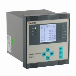
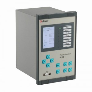
Microcomputer Protection Device,AM5SE
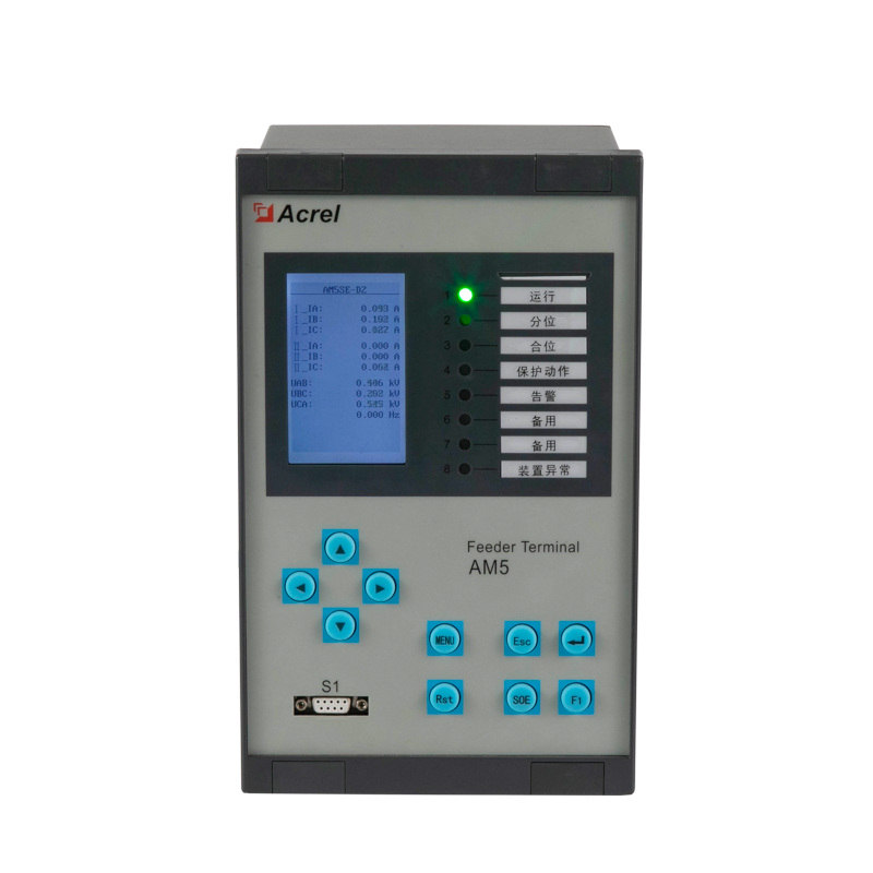
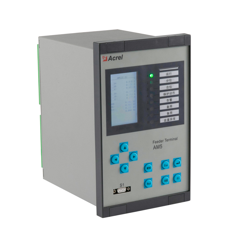
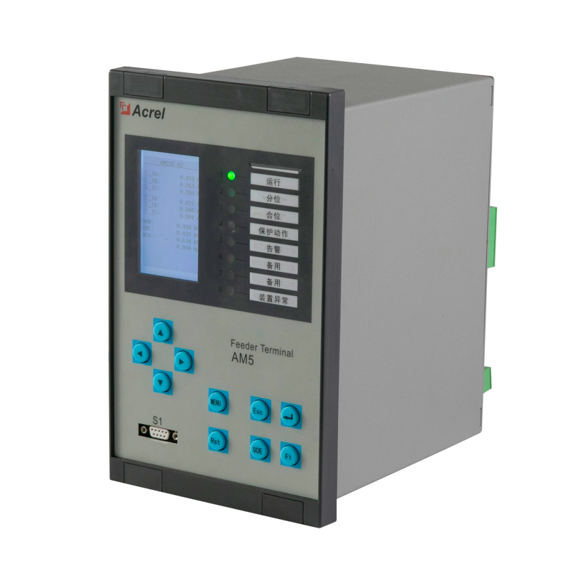
Microcomputer Protection Device,AM5SE
AM5SE series microcomputer protection measurement and control device (hereinafter referred to as the device) integrates protection, control, measurement, communication and monitoring functions, with rich resources, perfect configuration, convenient maintenance and stable performance, suitable for protection and measurement and control of power systems with voltage levels of 35kV and below , Realize the protection of incoming line, main transformer, distribution transformer, motor, capacitor, bus tie, PT, etc. The application fields cover electric power, water conservancy, transportation, petroleum, chemical industry, coal, metallurgy and other industries.
The hardware design of the device adopts reliability configuration, and the software is equipped with a special protection algorithm. It has strong anti-interference performance, high reliability, and flexible protection implementation methods. It can be used in conjunction with the Acrel-2000Z power monitoring system to provide guarantee for the safe and reliable operation of the power system. .
Rich protection functions
Feeder protection;
Transformer protection;
Voltage transformer supervision and parallel connection
Motor differential protection;
Motor protection;
Capactior protection;
Bus tie protection;
Transformer backup protection;
Transformer differential protection
Measurement
RMS current values;
RMS voltage values;
frequency;
Power factor;
RMS active power. RMS reactive power.

| AM5SEFunction |
-F |
-T |
-M |
-B |
-C |
-MD |
-D2 |
-D3 |
-TB |
-IS |
-K |
-UB |
|
Overcurrent (with compound voltage dependant,3 stages) |
√ |
√ |
|
√ |
|
|
|
|
√ |
√ |
|
|
|
Directional overcurrent (with voltage dependant,3 stages) |
√ |
|
|
√ |
|
|
|
|
√ |
√ |
|
|
|
Differential with Ratio restraining |
|
|
|
|
|
√ |
√ |
√ |
|
|
|
|
|
Instantaneous Differential |
|
|
|
|
|
√ |
√ |
√ |
|
|
|
|
|
CT supervision |
√ |
√ |
|
|
|
√ |
√ |
√ |
|
√ |
|
|
|
Overcurrent (2 stages) |
|
|
√ |
|
√ |
√ |
|
|
|
|
|
|
|
Directional earth fault (I01,2 stages) |
√ |
|
|
√ |
|
|
|
|
√ |
√ |
|
|
|
Directional earth fault (I02,2 stages) |
√ |
|
|
|
|
|
|
|
|
√ |
|
|
|
2 stages earth fault (I01) |
|
√ |
√ |
|
√ |
√ |
|
|
|
|
|
|
|
2 stages earth fault (I02) |
|
√ |
|
|
|
|
|
|
|
|
|
|
|
Overcurrent IDMT (Normal inverse,Very inverse, Extremely inverse) |
√ |
√ |
√ |
√ |
√ |
√ |
|
|
√ |
√ |
|
|
|
Earth fault IDMT (I01) |
√ |
√ |
|
|
|
|
|
|
√ |
√ |
|
|
|
Earth fault IDMT (I02) |
√ |
√ |
|
|
|
|
|
|
|
√ |
|
|
| Clearance zero sequence protection(2 stages) |
|
|
|
|
|
|
|
|
√ |
|
|
|
|
Positive sequence overcurrent (2 stages) |
|
|
|
|
|
√ |
|
|
|
|
|
|
|
Positive sequence overcurrent IDMT |
|
|
|
|
|
√ |
|
|
|
|
|
|
|
Negative sequence overcurrent (2 stages) |
|
|
√ |
|
|
√ |
|
|
|
|
|
|
|
Negative sequence overcurrent IDMT |
|
|
√ |
|
|
√ |
|
|
|
|
|
|
|
Overload |
√ |
√ |
√ |
|
|
√ |
|
|
√ |
√ |
|
|
|
Starting air-cooled water chiller |
|
|
|
|
|
|
|
|
√ |
|
|
|
|
On-load tap changer lock out |
|
|
|
|
|
|
|
|
√ |
|
|
|
|
Trip and close circuit supervision (alarm) |
√ |
√ |
√ |
√ |
√ |
√ |
|
|
√ |
√ |
|
|
|
Undervoltage (trip) |
√ |
|
√ |
|
√ |
√ |
|
|
|
√ |
|
|
|
Undervoltage (alarm) |
√ |
|
|
|
|
|
|
|
|
√ |
|
√ |
|
PT supervision |
√ |
√ |
√ |
√ |
√ |
√ |
|
|
√ |
√ |
|
√ |
|
Three phase auto-reclose |
√ |
|
|
|
|
|
|
|
|
√ |
|
|
|
Under frenquency |
√ |
|
|
|
|
|
|
|
|
√ |
|
|
|
Over frequency |
√ |
|
|
|
|
|
|
|
|
√ |
|
|
|
Post-accelerated overcurrent |
√ |
|
|
√ |
|
|
|
|
|
√ |
|
|
|
Overvoltage protection |
√ |
|
√ |
|
√ |
√ |
|
|
|
√ |
|
√ |
|
Blocking rotor |
|
|
√ |
|
|
√ |
|
|
|
|
|
|
|
Unbalance voltage |
|
|
√ |
|
√ |
√ |
|
|
|
|
|
|
|
Unbalance current |
|
|
|
|
√ |
√ |
|
|
|
|
|
|
|
Residual overvoltage protection |
√ |
|
|
|
√ |
√ |
|
|
√ |
√ |
|
|
|
Residual overvoltage (alarm) |
|
|
√ |
|
|
|
|
|
|
|
|
√ |
|
Positive sequence overvoltage protection |
|
|
|
|
|
√ |
|
|
|
|
|
|
|
Negative sequence overvoltage protection |
|
|
|
|
|
√ |
|
|
|
|
|
|
|
Non-electricity |
√ |
√ |
√ |
|
√ |
√ |
|
|
√ |
√ |
|
|
|
Starting time-out |
|
|
√ |
|
|
√ |
|
|
|
|
|
|
|
Directional power |
√ |
|
|
|
|
|
|
|
|
√ |
|
|
|
Thermal overload |
|
|
√ |
|
|
√ |
|
|
|
|
|
|
|
Incorrect phase sequence |
|
|
√ |
|
|
√ |
|
|
|
|
|
|
|
Voltage Phase loss |
|
|
√ |
|
|
√ |
|
|
|
|
|
|
|
BUS tie protection and standby power automatic switch |
|
|
|
√ |
|
|
|
|
|
|
|
|
|
FC block |
√ |
√ |
√ |
|
|
√ |
|
|
√ |
√ |
|
|
|
PT supervision and parallel connection |
|
|
|
|
|
|
|
|
|
|
|
√ |
|
Self-produced zero over current protection |
|
|
|
|
|
|
|
|
√ |
|
|
|
|
Synchro-check |
√ |
|
|
√ |
|
|
|
|
|
√ |
|
|
|
Rate of change of frequency |
|
|
|
|
|
|
|
|
|
√ |
|
|
|
Auto-close with voltage recovery |
|
|
|
|
|
|
|
|
|
√ |
|
|
|
Over haul-lockout |
√ |
|||||||||||